Week 4, Assignment 4
Electronic Production
Video - Week Four, Lecture Four
Goal
This week began with Electronics Production, we here need to produce a circuit. Through several techniques to build a circuit like bread-boarding, etching, etc., we mill the circuit in FabLab.
The aim of this week assignment is to make a Fab ISP Programmer. So, in this assignment I’ll be milling the PCB and will be stuffing the board with SMD components.
What is FabISP:
FabISP was a very new word for me at the beginning of this assignment as I never had any connection with Electronics before being from Mechanical Background. So I first went of net, discussed with some friends from electronic background and finally had some idea of it. So, the FabISP is an in-system programmer for AVR microcontrollers, designed for production within a FabLab. It allows you to program the microcontrollers on other boards you make.
PCB Material Selection:
PCB of various materials are available in market, each and every PCB are recommended for different purposes. So to have some more knowledge of PCB’s, I searched online and through the last lecture also I got a bit idea of various PCBs as of different grades such as FR-1, FR-2 and FR-4.
You can find More Information about them from the following link I refered:
FR-4 is fibreglass-based so, when it is milled it produces dangerous glass-shard dust, which makes it unpreferable to be milled and FR-1 being hard, flat material that consists of a thin layer of copper over a non-conductive phenolic resin makes itself quite easy to be milled on.
So, now after going through the knowledge I got and after discussing about the properties of FR-1 material, I found that it is very suitable for Milling on PCB Milling Machine. So, I picked FR-1 board to mill for the assignment.
What I Did:
As per the Lecture’s instruction given to us, so, from the Fab Academy 2017 page for Electronic Production week I have downloaded the files which are listed under hello.ISP.44.cad name, there were 3 different files for different purpose, which are as follows:
hello.ISP.44.traces – This file will be used to mill the traces
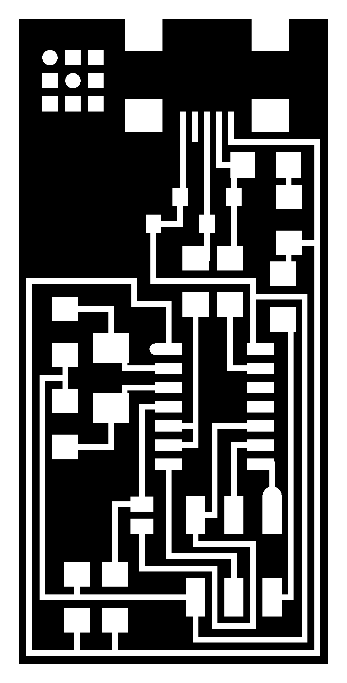
hello.ISP.44.interior – This file will be used to cut the board out from the main FR-1 PCB
hello.ISP.44 – This file will help me to solder the components at right place or a reference final board file
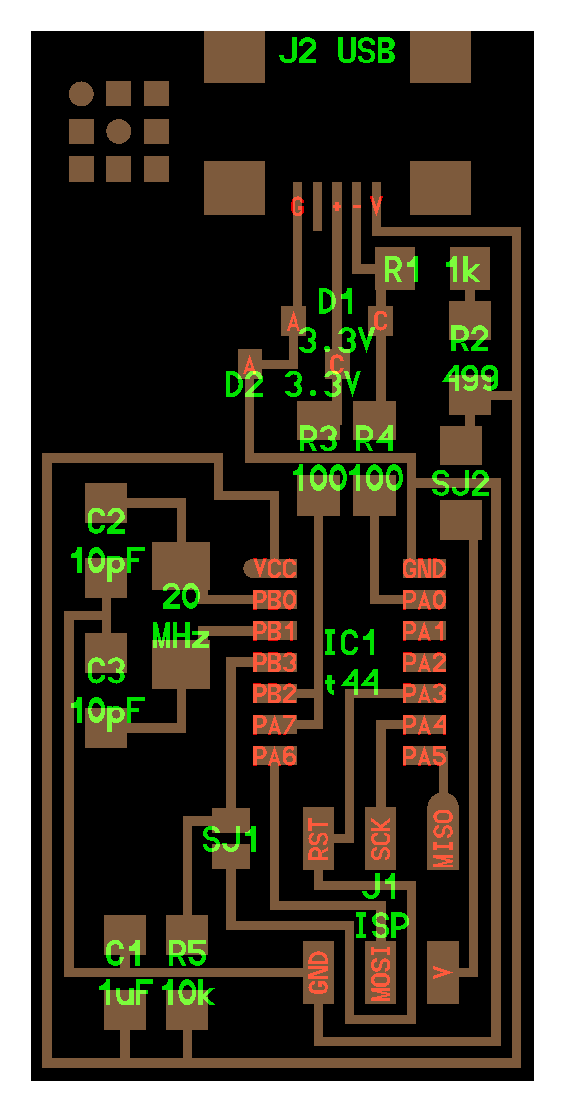
FabISP Board Diagram – This is the FabISP labelled board diagram that will help me to place components on board at right place
Installation of FAB Modules:
I already had Fab Module installed on my Computer so I didn't really tried installing the Fab Module again, but for the installing the Fab Module I am giving the exact procedure on the link below:
Preparation:
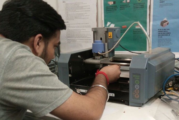
Roland Modela MDX-20
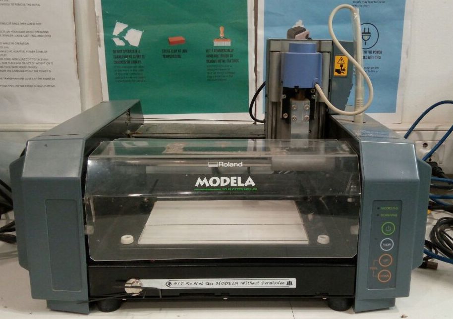
After downloading the circuits and cut-out files it was ready to be milled.
So to begin with milling first I stick a Piece of acrylic over the metal platform so that the Bit and the metal platform doesn’t get damaged as Modela is subtract material from the board through milling process.
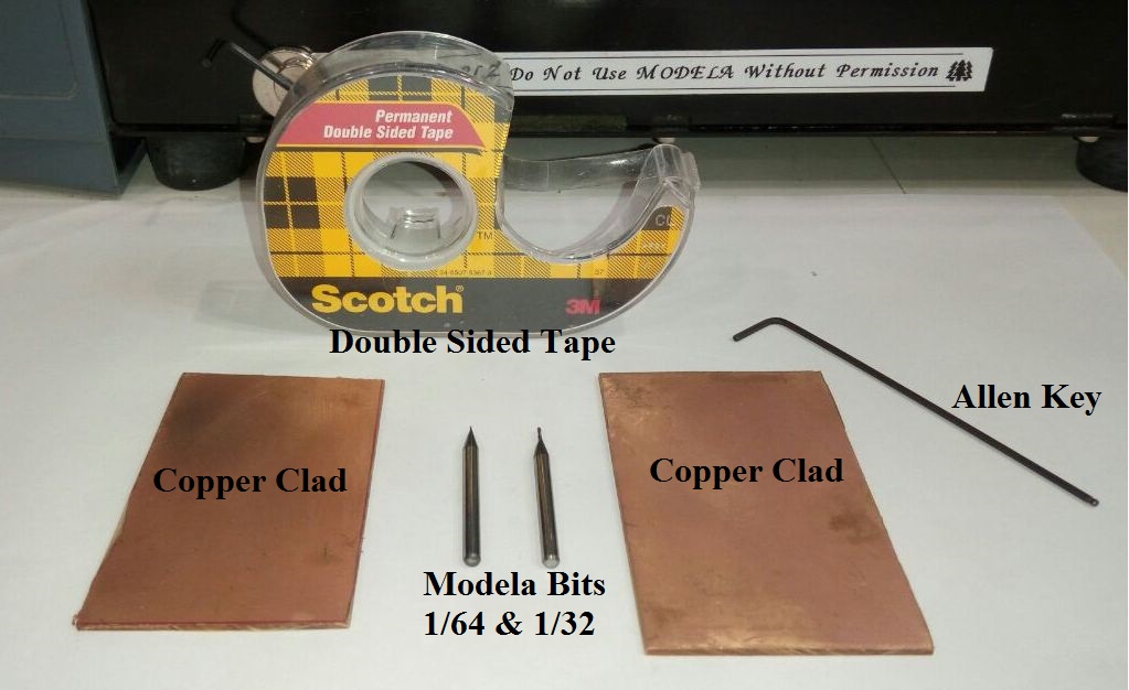
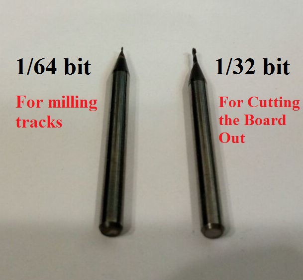
End Mills (Milling Tools) Used:
For Milling the trace 1/64 inch bit is used and for cutting or removing the milled board 1/32 inch bit is used.
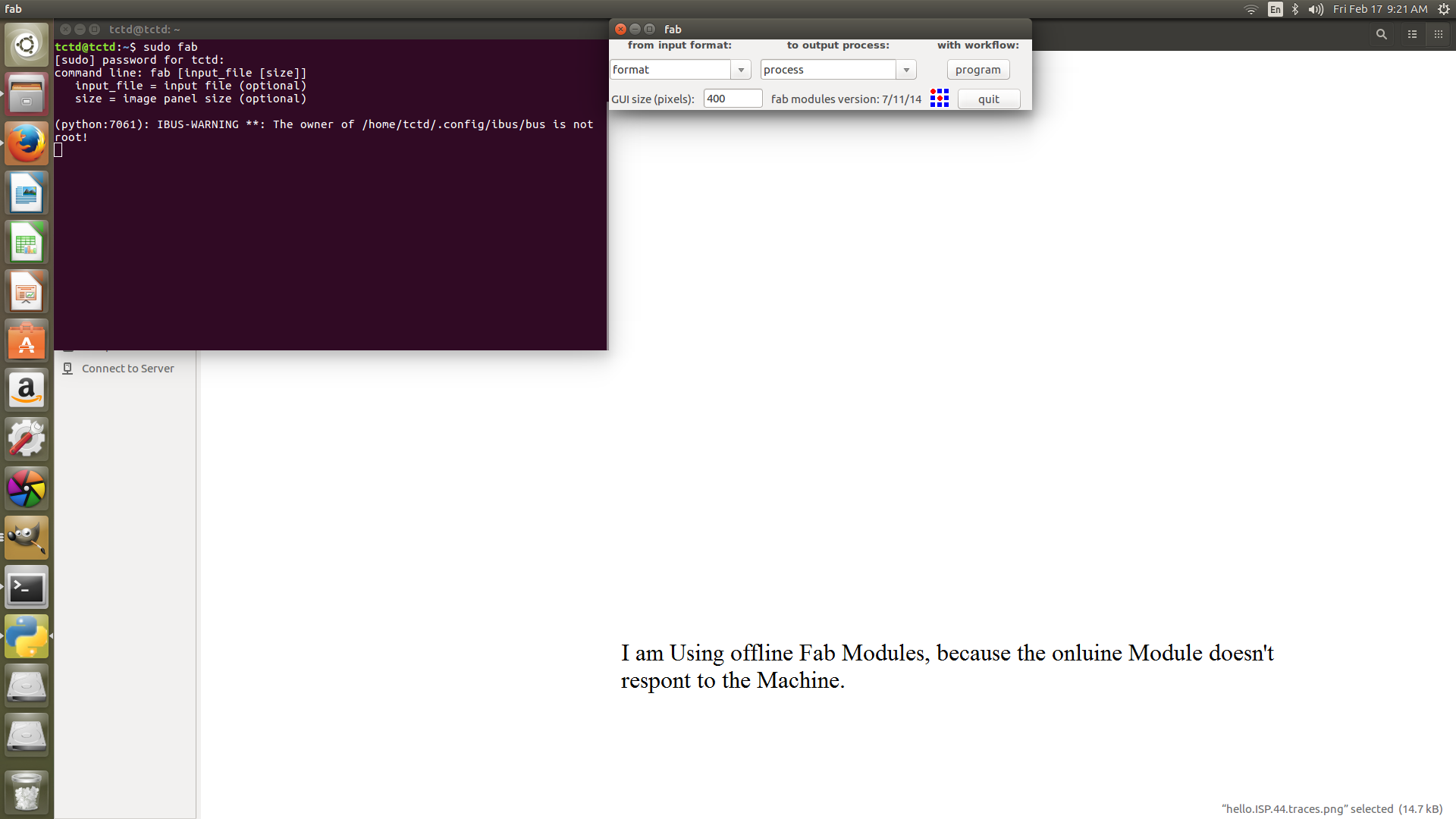
FAB Modules:
FAB Modules is used to run Roland Modela MDX-20.
Front Side Design:
To begin with, Open Terminal Window on Ubuntu OS by pressing “Ctrl+Alt+T” and Write “sudo fab” and hit Enter, then Fab Module page will get opened in that select respective things as follows:
Input Format : .png
Output Format: Roland MDX-20 mill (.rml)
Now Click “make_png_rml”
Select Mill trace as 1/64 and click on load .png.
Here now if any resizing or image editing is to be done, then make sure using “resize.png” and “invert.png” for inverting the color of board to be milled.
Now, make path – change the x(min) and y(min) position according to the space where the circuit is to be milled – and click on Move to x(min) and y(min) button – make .rml – make path – again make .rml – send it
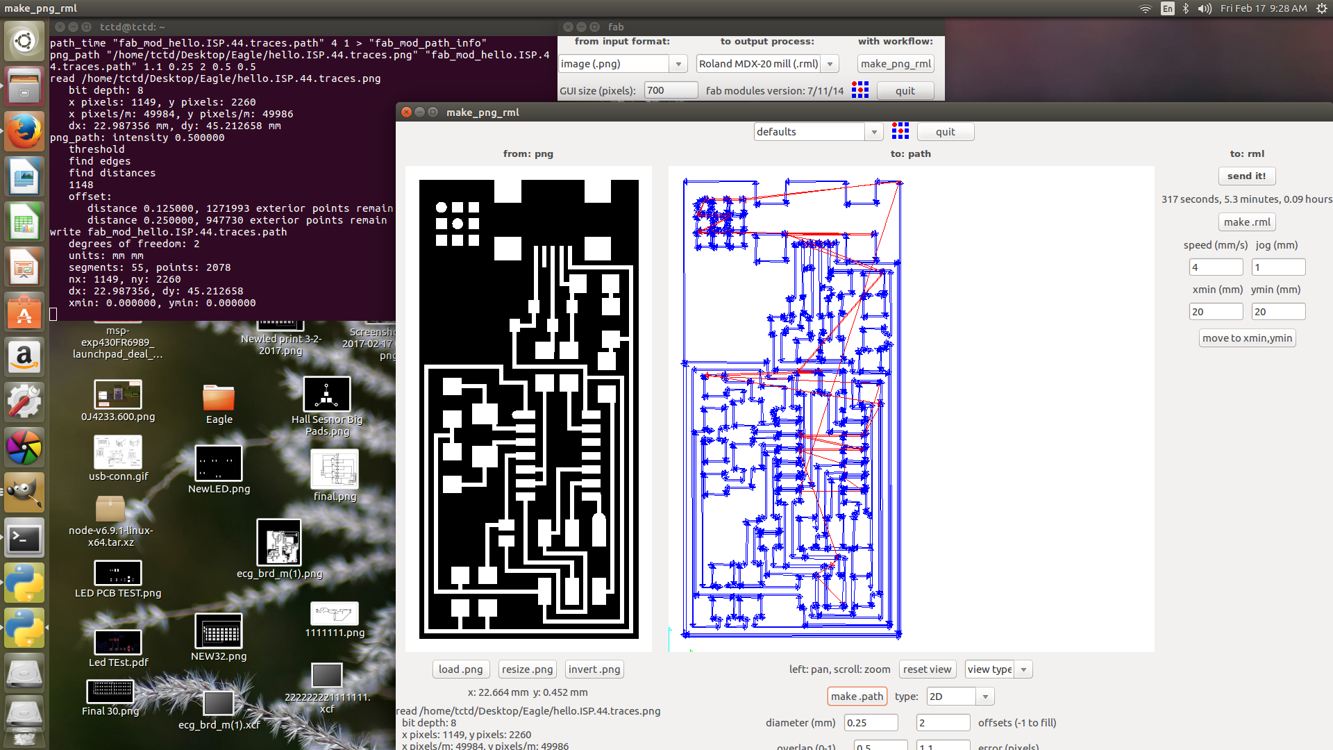
After that is shows a overview of the board, how the machine is going to mill, if it is all proper click the botton “begin milling” and the machine will start milling it.
But before clicking the “begin milling” button, I am suppose to make my modela ready for machine by adjusting the bit and setting it.
First for milling the board I used 1/64 inch bit and fitted it inside the collet of the spindle. The bit is supposed to be adjusted exactly touching the PCB surface as shown in below image.
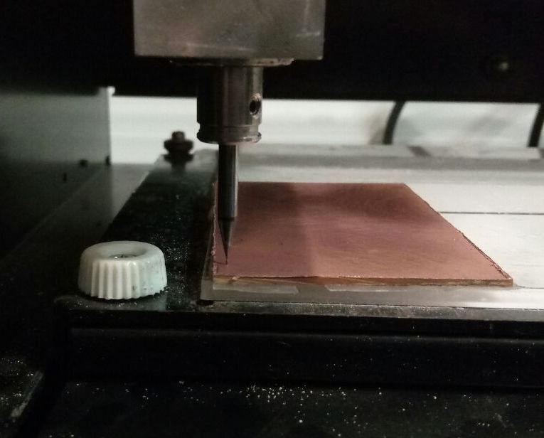
Now after setting the bit on PCB, Modela is perfectly ready to mill, so now I can click “begin milling” button on my PC Screen and enjoy the modela track milling process.
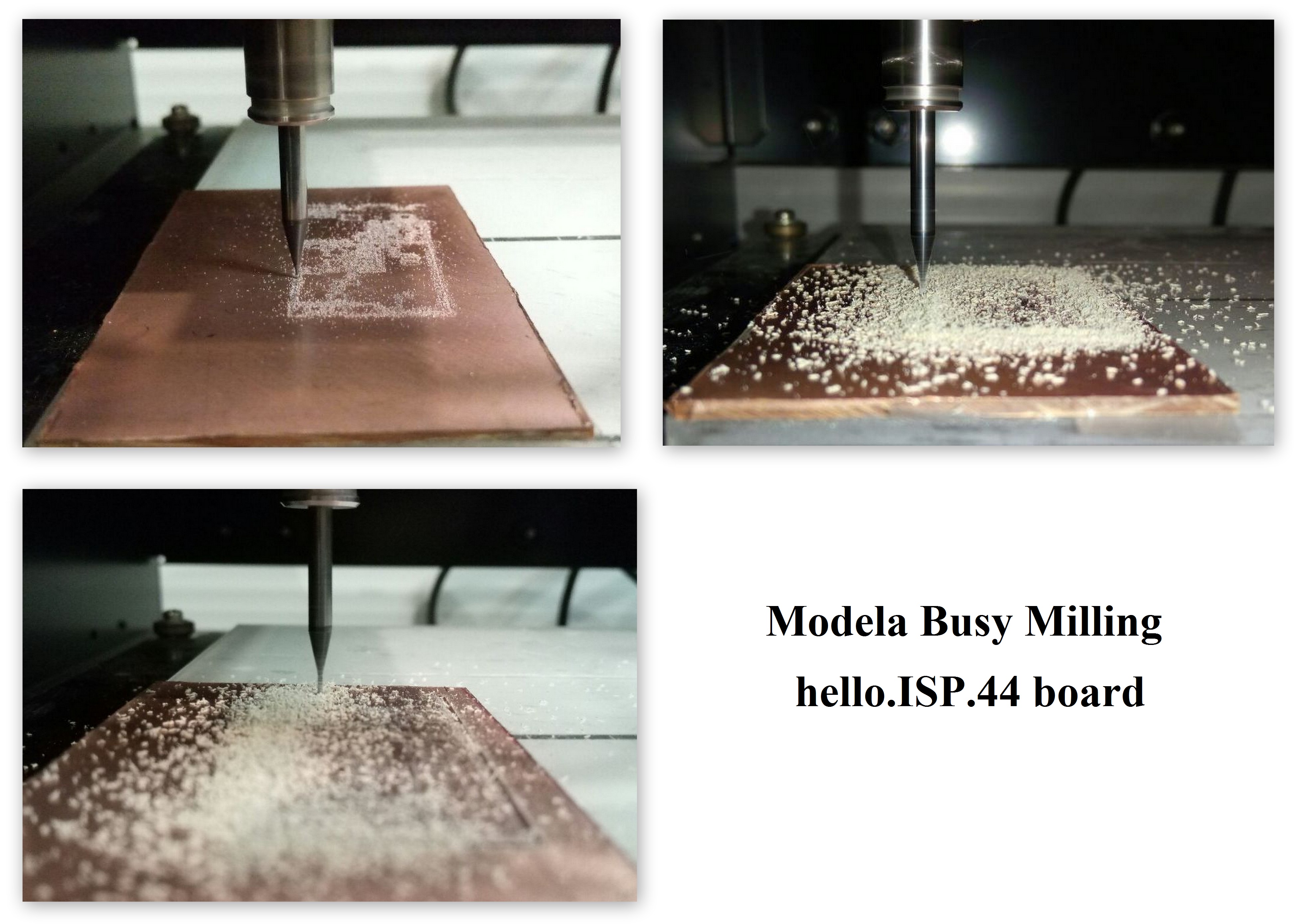
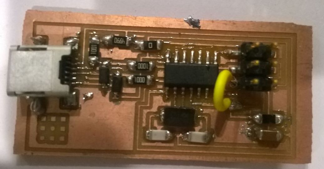
Milled Board:
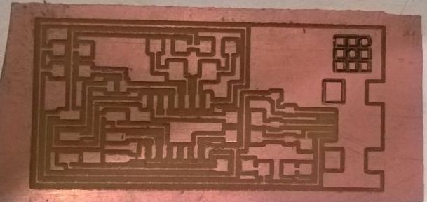
Now I have my board milled perfectly. Now, I can stuff the board with the components.
Components:
These are the components I needed to stuff the board:
| 1 ATTiny 44 microcontroller | 1 Capacitor 1uF |
| 2 Capacitor 10 pF | 2 Resistor 100 ohm |
| 1 Resistor 499 ohm | 1 Resistor 1K ohm |
| 1 Resistor 10K | one 6 pin header |
| 1 USB connector | 2 jumpers - 0 ohm resistors |
| 1 Cystal 20MHz | 2 Zener Diode 3.3 V |
| one usb mini cable | one ribbon cable |
| two 6 pin connectors |
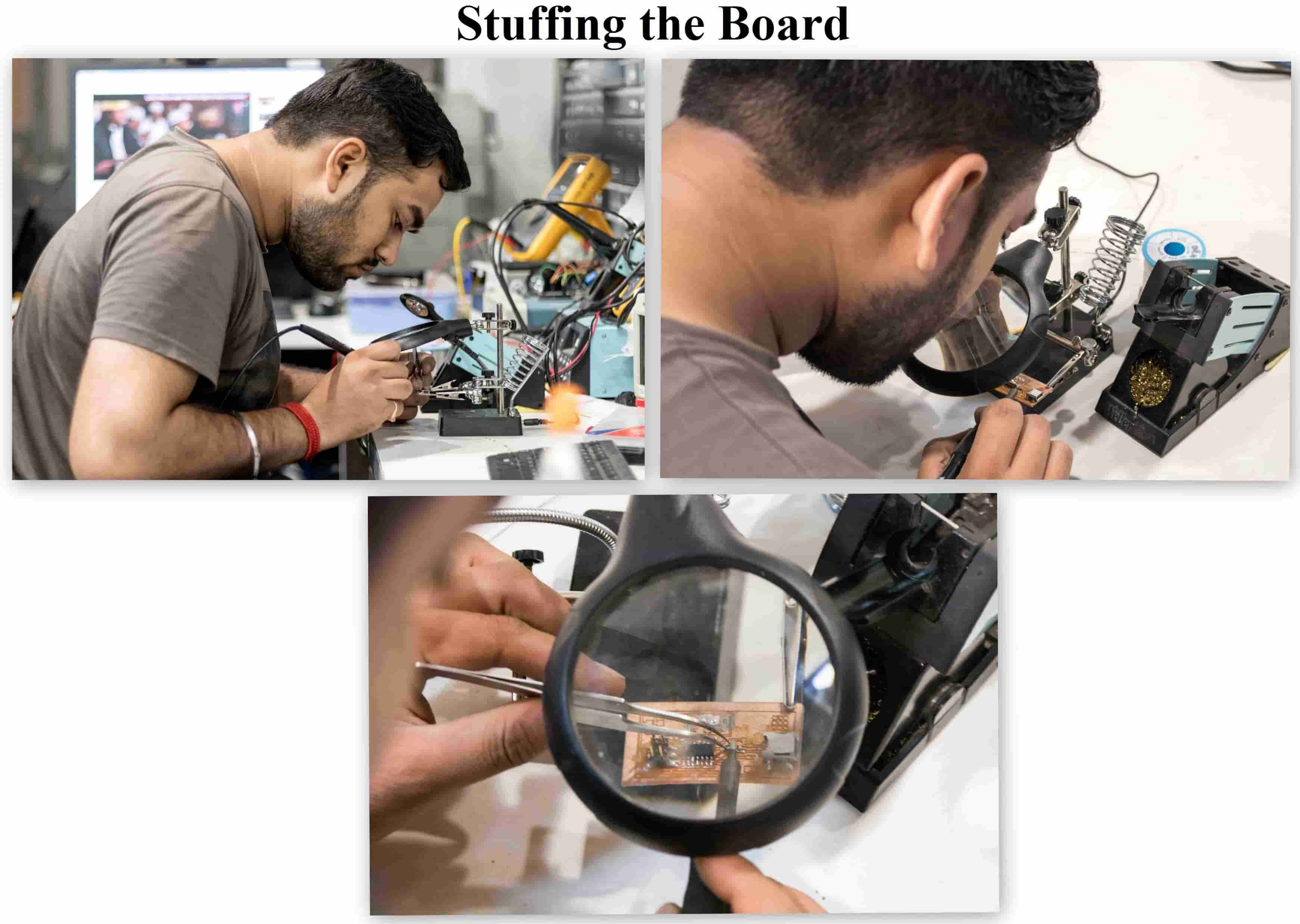
Stuffing the Board:
After getting all the components I started stuffing the board. As I had very little experience doing soldering I first started with soldering SMD’s on another board which was waste for me and made my hand clean over that and then started soldering the real board.
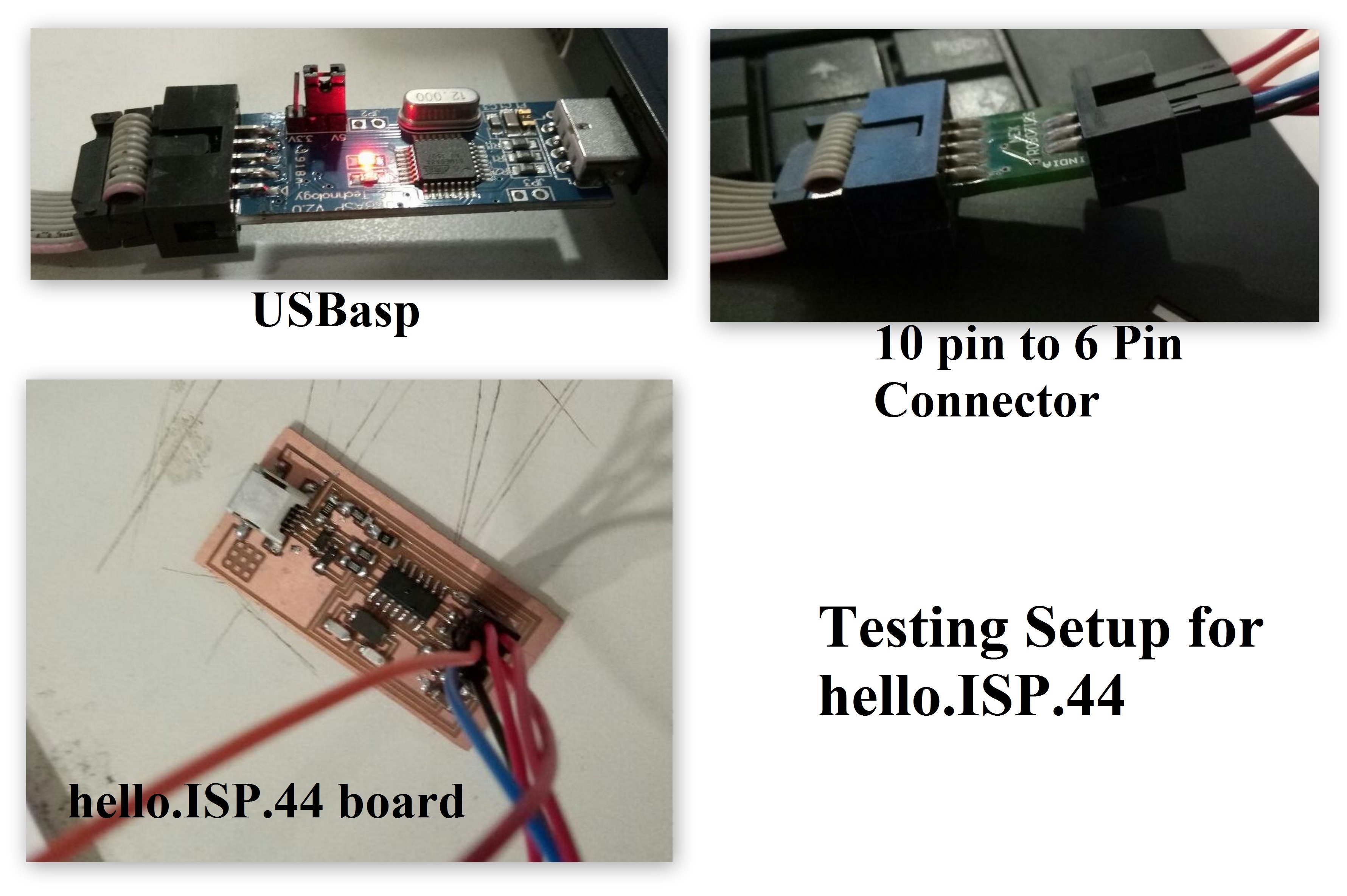
Programming the FabISP:
For programming the FabISP board I used:
1. USPasp as a Programmer
2. 10 Pin to 6 Pin Connector which converts USBasp 10 pins to 6 Pins
3. FabISP as my Target board
Testing the FabISP
After making the FabISP board it was now time to test the board.
Smoke Test
I performed the smoke test by just pluging my FabISP board with a MINIUSB cable to my Computer and checked what notification Computer give by just suppling power through Board.
So fortunately my this test went Fine. Computer showed no error after plugging the Board.
Now the real test was to Program by using a Programmer. So here I used a USBasp to program by FabISP board.
Programming
To begin with I first checked the indication whether the board is working or not, so simply after connecting it with the computer I opened the Terminal window and wrote the below command line which listed out all the USB devices connected to the Computer.
lsusb grep usbasp #command lists out all the USB connectedAfter executing the above command in the terminal window I got the list of all connected USB devices via USB port.
If the terminal returns nothing after the command execution it means that the FabISP is not working correctly. If it returns a line with the device id and bus number its an indication of FabISP working properly.
Setting up FabISP
For this now I used another Micro-Controller board which was working, and connected it to the FabISP using the Jumper Wires. The connection between the two were as follows.
FabISP - USBasp
MISO - MISO
MOSI - MOSI
SCK - SCK
GND - GND
VCC - VCC
Then I connected my USBasp to the Computer via its USB and gave the command in the terminal window
sudo avrdude -c USBasp -p m8 -P usb -U signature:r:"/home/tctd/signature.hex":i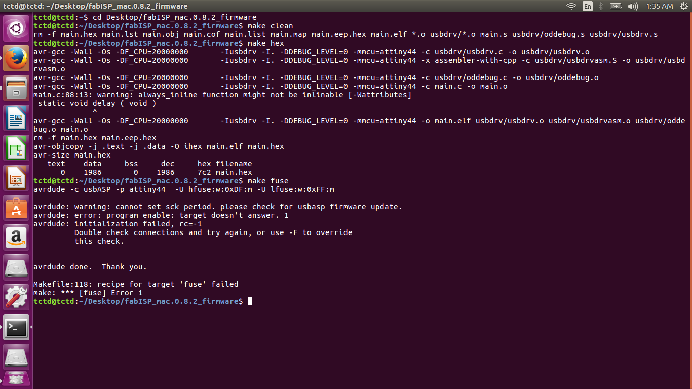
I got the above Error
So I tried number of time again and again, tried changing the MISO to MOSI pin and MOSI to MISO pin, tried changing the USBasp Programmer board, milled a new board soldered and againg tried the same, but til now I didn't got the solution. Still struggling with the same Error.
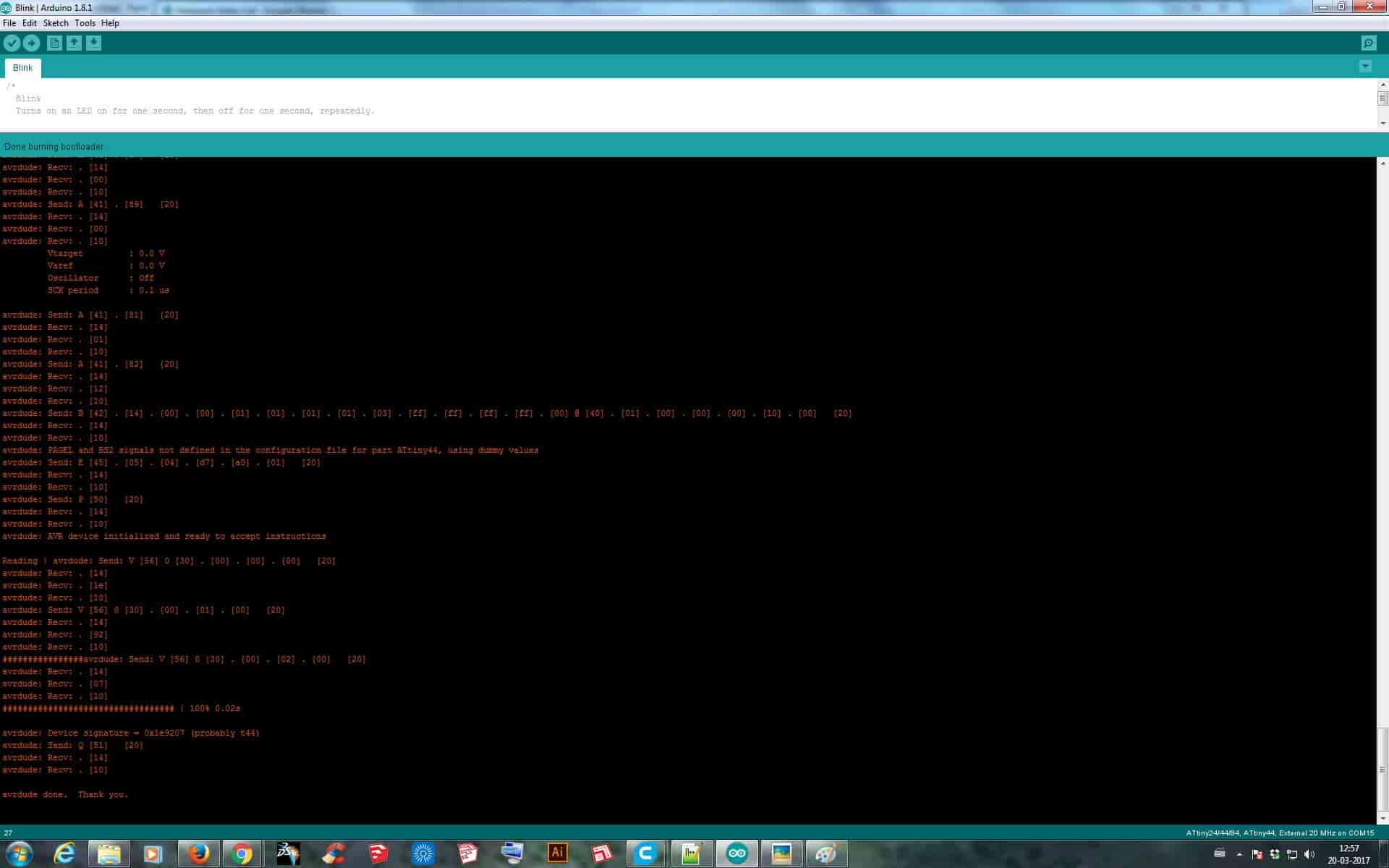
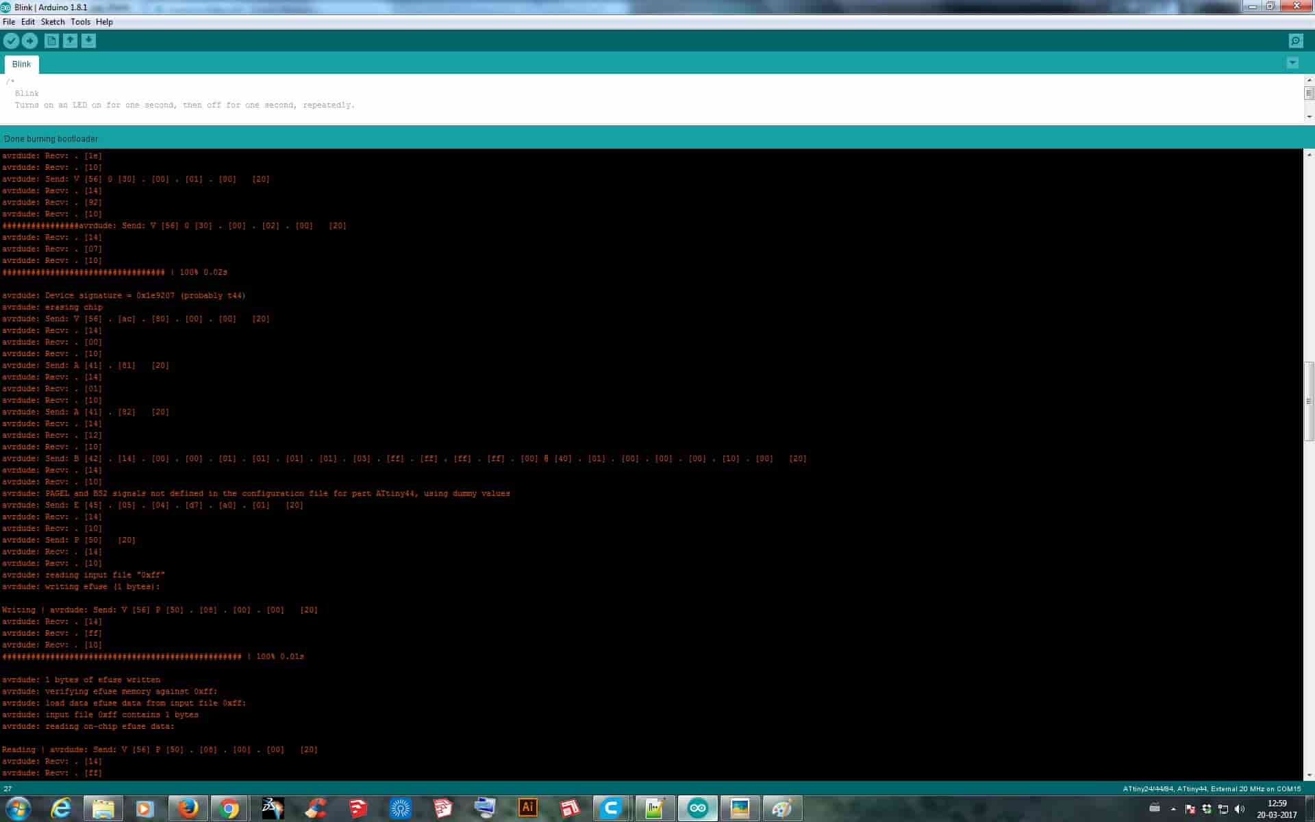
After getting fed up with number of iterations I then decided to burn the FabISP using Arduino IDE 1.8.1. So I then started doing all the settings required in the Arduino software for adding boards and all with the help of steps given in this tutorial, and simply run the command "Burn Bootloader" in the tools drop-down menu. Finally then it got burned anfd showed the signature of the microcontroller I used.
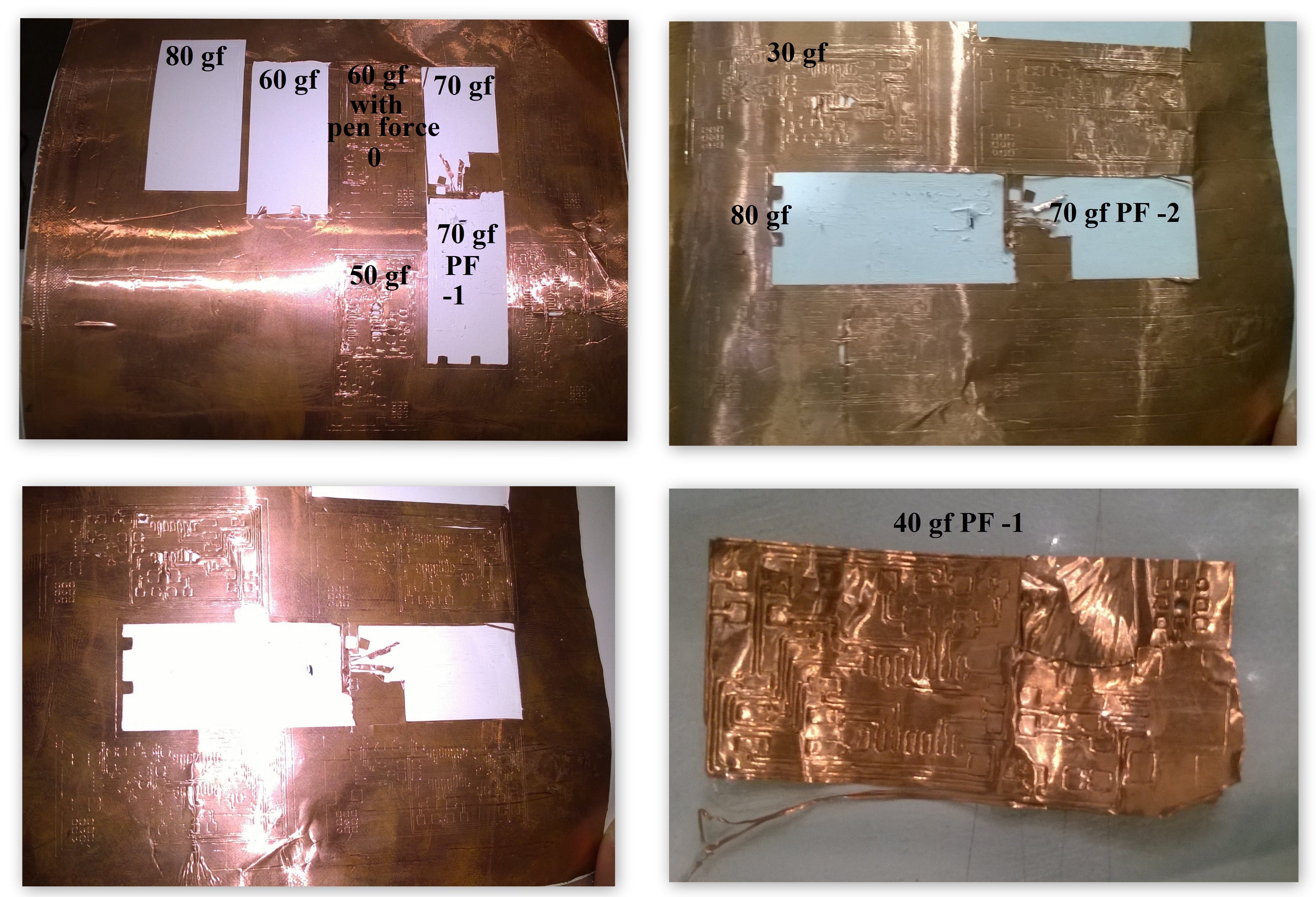
Flexible Circuit Cutting:
As per our Lecture and instructions given about this assignment, I preferred trying to print a Flexible circuit too. So I first converted my hello.ISP.44.cad file to vector format so that the Vinyl Cutter can cut it properly by using CoralDraw. After converting, I switched the Vinyl Cutter ON and placed my Copper Vinyl Roll on the machine. Before give the cut I knew that it would not cut the Copper roll in the first chance as I was going to cut it for the first time without any knowledge of Force Setting for Copper Roll to cut. So firstly I began with adjusting the force to “40gf” and gave the print, but it didn’t got cut, it just marked the outline on the Copper Roll but didn’t went through. Now again on trial and error basis the increased and lowered the Force but didn’t had the desired output. I went till maximum Force of “80gf” but at this force it scrambled the whole area which I was cutting and again the output was nothing. I even tried to adjust the Pen Force manually but still didn’t had the result. So finally after trying for more than 15 times I got tired with it and skipped the plan of making a Flexible Circuit.